Site Requirements for a New Brewhouse Installation
Tanks arrive on a truck; the room they stand in has to exist first. Fall to the drain, floor loading, clear height above the tallest vessel, water flow, heat source, glycol space and ventilation are the seven items that decide whether installation takes a fortnight or a season, and all seven are easier to fix on paper.

Key takeaways
- Screed a fall of about 10 mm per metre towards a 300 mm wide trench, so a 12 m brew house floor drops roughly 120 mm from the far wall.
- A full 1,000 L vessel can put on the order of 310 kg on each of four legs under an assumed loading, which is a number the structural engineer needs before the slab is poured.
- Plan near 5 L of water per litre of beer brewed once cleaning is included, with a buffer tank and a refill rate of 20-30 litres a minute.
- Match the heat source to the plant room: an element bank, a steam boiler with its flue and blowdown, or direct fire with its own gas and clearance rules.
Fix the Size Class Before You Fix the Floor Plan
Every other requirement follows the volume. The published hem brew system listings run from a 200 L nano set through 300 L, 500 L, 1,000 L, 2,000 L, 2,500 L, 5,000 L and 10,000 L (10 T) configurations, and the difference between the smallest and the largest is the difference between a back room and a warehouse. Choose the class first, then lay the utilities around it, because the trench, the slab thickness and the electrical supply all follow the vessel set.
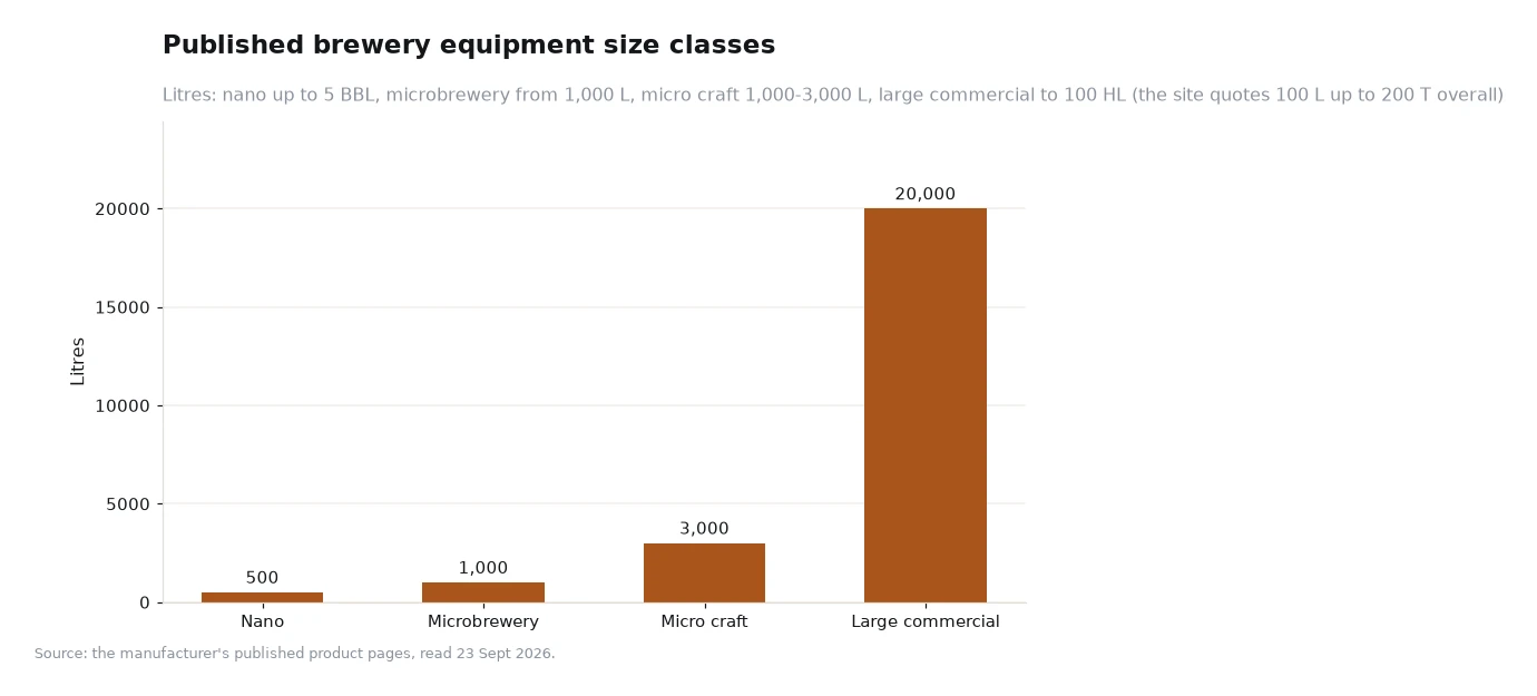
The size ladder published on the manufacturer's product pages runs from nano sets of about 500 L, through a microbrewery floor of 1,000 L and a micro craft band of 1,000-3,000 L, up to large commercial plant at 20,000 L (20 T), with the site quoting 100 L to 200 T overall. A 500 L room and a 20,000 L room share the same seven requirements; they simply multiply the numbers.
Floor Fall, Trench and Floor Loading
Brewing is a wet process with sugar in the water, and a floor that pools is a floor that grows a biofilm. Design a fall of roughly 10 mm per metre towards a trench 300 mm wide and 250-300 mm deep with a removable grate, positioned so that no vessel is more than a few metres from a drain. In a 12 m long room that fall means the slab drops about 120 mm from the far wall to the trench, which is a decision made by the bricklayer and regretted by everyone else if it is skipped.
Loading is the second floor question. Assume a filled 1,000 L vessel weighs about 1,250 kg and stands on four legs, which is roughly 310 kg per leg as a point load; a 2,000 L vessel doubles it. Passing that figure to the structural engineer early is what stops the tank feet from dimpling a screed or sitting out of level, because a vessel out of level drains badly and its jackets do not fill evenly.
Headroom Above the Tallest Vessel
Ceiling height is measured from the top of the tallest piece of equipment, not from the grid. Add the shell height, the legs, the clearance to open a manway or lift a kettle lid, the insulation and pipework, and then a working margin. A 1,000 L vessel set with an assumed 2,100 mm shell, 450 mm legs, 350 mm of manway swing and 250 mm of cladding and pipes needs about 3,150 mm of clear height, so a 3.2 m room is the sensible minimum and a 3.5 m room is the comfortable one for the 2,000 L class.
The same arithmetic governs access: sieve plates, sparge arms and the manway gasket all need room to come out, and a tank under a low soffit turns a fifteen-minute job into a scaffold hire. If the building already stands, measure the lowest obstruction on the route in before confirming the vessel dimensions.
Water, Heat, Glycol and Ventilation
Water arrives in bursts rather than at an average. A 1,000 L brew day with cleaning is assumed to draw about 5,000 L, so a 2,000 L buffer tank refilled at 30 litres a minute supports the day with a 67-minute refill window between draws. Test the mains for flow and pressure rather than pipe size, and have the water analysed for hardness and chloride.
Then settle the heat source, because it decides the plant room. An electric element bank needs a supply sized for its total load and a panel with the right protection; a steam boiler needs fuel, a flue, blowdown and water treatment; direct fire needs gas, combustion air and its own clearances. This is where Hermann's engineers expect the awkward questions, because installation and commissioning sit inside the turnkey scope. Add glycol next: the chiller needs airflow, a level base and a short, insulated run to the tanks, and the CIP station needs a drain, water and bunded storage for caustic. Finally, ventilate the kettle with a condensate hood and enough extraction to clear the boil.
| Site item | Planning figure used here | What it decides |
|---|---|---|
| Floor fall and trench | About 10 mm per metre to a 300 mm wide trench | Whether spilled wort and cleaning water leave the room instead of pooling under the vessels |
| Floor loading | A full 1,000 L vessel at roughly 310 kg per leg on four legs | Whether the slab carries the load and whether the feet stay level for the life of the tank |
| Clear height | About 3,150 mm for a 1,000 L set; plan 3.2-3.5 m | Manway access, insulation and the ability to lift a kettle lid or a sieve plate |
| Water | About 5 L per litre brewed, with a buffer tank and a 30 L/min refill | Brew day length, because brewing and cleaning draw water in bursts |
| Glycol | Chiller with airflow and a short insulated run to the tanks | Fermentation control, which is cheap to provide at build stage and expensive afterwards |
| Ventilation | A condensate hood over the kettle with extraction to clear the boil | Whether the room stays workable on a brewing day |
Worked example
The numbers below are a worked example for one assumed room, not a specification for yours. Assumptions: a room 12 m long and 6 m wide, a 1,000 L vessel set against the long wall, a trench along the far wall, and a ceiling with one 400 mm deep duct crossing the room.
Drainage first. A fall of 10 mm per metre across 12 m gives 12 x 10 = 120 mm of drop from the high end of the floor to the trench lip. Add 250 mm of trench depth and the excavation is 370 mm below the high point of the slab, so the finished floor level must be set at least 370 mm above the structural slab, or the trench gets a pumped sump instead. That figure decides the door threshold and the loading bay.
Headroom second. Shell 2,100 mm + legs 450 mm + manway swing 350 mm + cladding and pipework 250 mm = 3,150 mm. The room measures 3,400 mm to the soffit, but a duct hangs 400 mm below it, leaving 3,000 mm over part of the floor, which is 150 mm short. Moving the duct or shifting the vessel clear takes an afternoon; discovering it on installation day costs a week.
Utilities third. With 5,000 L drawn on a brew day and a mains flow of 25 litres a minute, a direct feed would need 5,000 / 25 = 200 minutes of continuous flow, which no mains tap delivers in practice. A 2,000 L buffer tank filled overnight covers 40% of the day instantly, and the remaining 3,000 L refills in 3,000 / 30 = 100 minutes spread across the brew and the clean.
Frequently asked questions
What clear height does a brewhouse installation need?
Measure from the top of the tallest vessel and add everything above it. For a 1,000 L set with an assumed 2,100 mm shell, 450 mm legs, 350 mm for a manway and 250 mm of cladding and pipes, the requirement is about 3,150 mm, so plan on 3.2 m as a minimum and 3.5 m for the 2,000 L class.
How much water should be planned for a brew day?
Plan near 5 L of water per litre of beer brewed once cleaning is counted. A 1,000 L brew day therefore draws about 5,000 L, and a 2,000 L buffer tank refilled at 30 litres a minute covers the peaks with a refill window of roughly 100 minutes between draws.
Bring the Site Plan to the First Conversation
A dimensioned plan of the room, the drain positions, the supply sizes and the ceiling obstructions is the most useful document a buyer can send before a quotation is written, because it moves the conversation from vessel options to a layout that fits.
The brewery equipment range shows the sizes that have to be accommodated, the company background explains the design and installation support behind them, and the contact page is where a photographed plant room belongs.
Then sequence the works properly: slab and trench, then walls and the boiler or panel, then the floor finish, then the tanks. Installation crews can work around a missing shelf; they cannot work around a floor that has not been poured, and no supplier can shorten the published delivery window to rescue a building programme that started late.
Published figures here come from the manufacturer's own website (hembrewing.com), read 23 Sept 2026: the system sizes, the size classes and the installation and technical support offered with a turnkey project. Drain falls, loadings, water volumes and heights are the author's own labelled assumptions for one example room.[1]